Copper & Fiber Certification
Companies expect their twisted pair cabling to work flawlessly, but corners cut during design, installation and testing result in network downtime which translates to wasted resources and lost revenue. This can be avoided by cable installers that are capable of certifying cabling installations to industry standards and network technicians who can find faults quickly. From 100BASE-T to tomorrow’s advanced twisted pair technology, Fluke Networks is the industry’s most trusted partner for cabling certification.


Data centers and enterprises rely heavily on optical fiber cabling to support the exploding demand for bandwidth, so being able to test its quality is critical to maximize network performance and up time. Fluke Networks’ industry-leading portfolio of innovative fiber optic cable test and certification solutions are used worldwide by technicians and installers because of their ease-of-use, accuracy, and durability.
Optical Time Domain Reflectometer (OTDR)

The Optical Time Domain Reflectometer (OTDR) is useful for testing the integrity of fiber optic cables. It can verify splice loss, measure length and find faults. The OTDR is also commonly used to create a “picture” of fiber optic cable when it is newly installed. Later, comparisons can be made between the original trace and a second trace taken if problems arise. Analyzing the OTDR trace is always made easier by having documentation from the original trace that was created when the cable was installed.
OTDRs are most effective when testing long cables (more than aproximatley 250 meters or 800 feet) or cable plants with splices. The data that the OTDR produces are typically used to create a picture called a “trace” or “signature” that has valuable information for the trained user and can be stored for later reference or to check against a blueprint when network trouble arises. OTDRs should not be used for measuring insertion loss in the fiber optic cable – that task is better left to a fiber optic test source and power meter. OTDRs simply show you where the cables are terminated and confirm the quality of the fibers, connections and splices. Of course, OTDR traces are also used for troubleshooting, since they can show where breaks are in fiber when traces are compared to installation documentation.

Fiber Optic Splicing
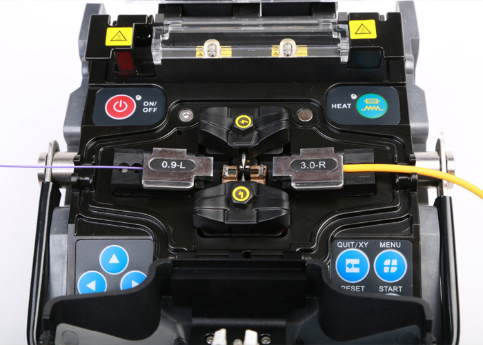
Simply put, fiber optic splicing involves joining two fiber optic cables together. The other, more common, method of joining fibers is called termination
There are two methods of fiber optic splicing, fusion splicing & mechanical splicing. Advanced network technologies perform the both splicing methods according to the clients & technical requirements


